

Single Phase Motor Wiring Diagram with Capacitor Start PDF: A Comprehensive Plan
This PDF details capacitor-start motor wiring, offering diagrams for 2 & 3-terminal capacitors, troubleshooting, safety, and component identification for reliable operation․
Capacitor start motors are a prevalent type of single-phase induction motor, widely utilized across diverse applications like pumps, compressors, and industrial machinery․ Their defining characteristic lies in the incorporation of a capacitor within the auxiliary winding circuit during startup․ This capacitor introduces a phase shift, creating a temporary two-phase effect, significantly boosting starting torque – a crucial feature for loads requiring substantial initial power․
Understanding these motors necessitates a grasp of their wiring intricacies․ A detailed wiring diagram, often found in PDF format, is essential for correct installation and maintenance․ These diagrams illustrate the connections between the main winding, auxiliary winding, starting capacitor, and a centrifugal switch or relay, ensuring safe and efficient operation․ Proper wiring is paramount to prevent overheating and ensure longevity․
Understanding Single Phase Motor Basics
Single-phase motors operate on a single alternating current (AC) power supply, commonly found in residential and light commercial settings․ Unlike three-phase motors, they require a starting mechanism because they lack inherent starting torque․ The stator, containing the main and auxiliary windings, generates a rotating magnetic field․ The rotor, typically a squirrel-cage design, interacts with this field to produce rotational motion․
A key aspect is understanding the role of windings․ The main winding is continuously energized, while the auxiliary winding is only active during startup․ A capacitor, integral to capacitor-start motors, shifts the phase of the current in the auxiliary winding, creating the necessary torque․ A PDF wiring diagram clarifies these connections, vital for proper function and safety․
Why Use a Capacitor Start Motor?
Capacitor-start motors excel in applications demanding high starting torque, like compressors, pumps, and conveyors․ They offer a significant advantage over other single-phase motor types, providing the power needed to overcome initial inertia․ This is achieved through the capacitor’s phase-shifting effect, boosting the magnetic field and enabling robust startup performance․
These motors are cost-effective and relatively simple to wire, making them popular for various industrial, commercial, and agricultural uses․ A detailed wiring diagram PDF is crucial for correct installation and maintenance․ They provide a balance between starting capability and running efficiency, making them a versatile choice․
Key Components of a Capacitor Start Motor
A capacitor-start motor’s functionality relies on several key parts․ The stator windings – main and auxiliary – create the rotating magnetic field․ The rotor is the rotating part, driven by this field․ Crucially, the starting capacitor provides the necessary phase shift for initial torque․
A centrifugal switch or relay automatically disconnects the capacitor once the motor reaches a certain speed, preventing overheating․ Understanding each component’s role is vital when referencing a wiring diagram PDF․ Correct identification of these parts ensures proper wiring and optimal motor performance, extending its lifespan and efficiency․
Stator Windings (Main & Auxiliary)
The stator windings are fundamental to a capacitor-start motor’s operation․ The main winding, typically with more turns, is responsible for sustaining the motor’s rotation once started․ The auxiliary winding, having fewer turns, is energized only during startup with the aid of the capacitor․
This capacitor creates a phase difference, generating the initial torque․ Wiring diagrams clearly illustrate how these windings connect to the power source and capacitor․ Correctly identifying and connecting these windings, as shown in a PDF diagram, is crucial for successful motor operation and preventing damage․
Rotor
The rotor is the rotating component within a single-phase capacitor-start motor, typically a squirrel-cage design consisting of conductive bars embedded in a laminated iron core․ Its function is to convert the magnetic field produced by the stator windings into mechanical rotation․
While wiring diagrams primarily focus on the stator connections, understanding the rotor’s role is vital․ The induced currents within the rotor bars interact with the stator’s magnetic field, creating torque․ A properly functioning rotor is essential for the motor to run efficiently after the capacitor-assisted start․ PDF resources often include cutaway diagrams illustrating rotor construction․
Starting Capacitor
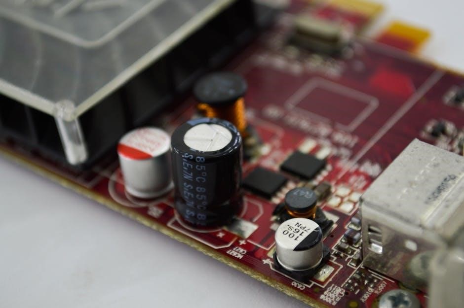
The starting capacitor is a crucial element in a capacitor-start motor, temporarily shifting the phase of the current in the auxiliary winding․ This phase shift creates a rotating magnetic field, providing the necessary torque to initiate motor rotation․ PDF wiring diagrams clearly illustrate its placement across the auxiliary winding terminals․
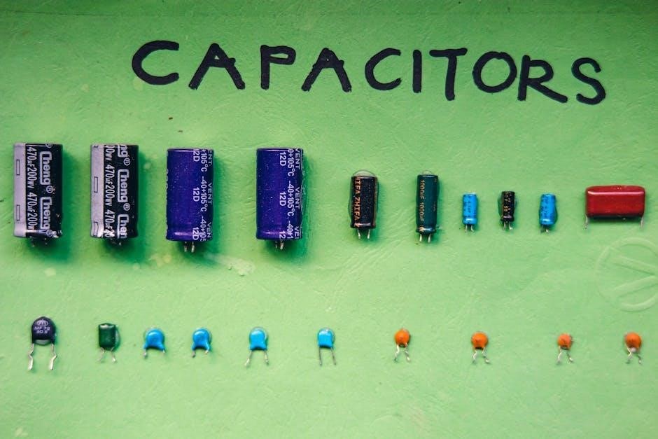
Capacitor values (measured in microfarads ― µF) are specific to the motor and are vital for proper starting․ Using an incorrect capacitor can lead to starting failure or overheating․ These capacitors are typically non-polarized and designed for intermittent duty, as they are switched out of the circuit once the motor reaches a certain speed․

Centrifugal Switch/Relay
The centrifugal switch, or relay, is a vital safety component in capacitor-start motors, automatically disconnecting the starting capacitor and auxiliary winding once the motor reaches approximately 75-80% of its rated speed․ PDF wiring diagrams showcase its integration into the circuit, ensuring the capacitor isn’t continuously energized․
This prevents overheating and potential damage to the capacitor and auxiliary winding․ Relays offer a more reliable and quieter alternative to centrifugal switches, especially in demanding applications․ Proper functioning of this switch/relay is critical; failure to disconnect the starting circuit can cause significant motor damage․

Capacitor Start Motor Operation Principle
Capacitor-start motors leverage a phase shift created by the starting capacitor to generate a rotating magnetic field, initiating torque․ PDF diagrams illustrate how the capacitor, connected in series with the auxiliary winding, advances the current in this winding relative to the main winding․
This phase difference produces the necessary starting torque, overcoming the motor’s initial static friction․ Once the motor gains speed, the centrifugal switch (or relay) disconnects the auxiliary winding and capacitor, allowing the motor to run solely on the main winding․ Understanding this principle is key to interpreting wiring diagrams and troubleshooting․
Wiring Diagram Fundamentals
Wiring diagrams for capacitor-start motors visually represent electrical connections․ PDF resources emphasize understanding symbols for components like capacitors, windings, and switches․ Diagrams typically show the main winding connected directly to the power source, while the auxiliary winding, alongside the starting capacitor, forms a separate circuit․
The centrifugal switch’s role in disconnecting the auxiliary circuit upon reaching a certain speed is clearly depicted․ Accurate interpretation requires recognizing common terminal designations (C, R, S, H, F) and wire color coding․ These fundamentals are crucial for safe and effective motor wiring, as detailed in the PDF guides․
Identifying Motor Terminals
Accurate terminal identification is vital when referencing a capacitor-start motor wiring diagram PDF․ Common designations include ‘C’ for Common, ‘R’ for Run, ‘S’ for Start, ‘H’ for Hermetic (compressor), and ‘F’ for Fan․ Understanding these codes prevents incorrect connections․
PDF resources highlight wire color coding conventions, though variations exist․ Typically, black or red indicates the main winding, while other colors denote the auxiliary winding and capacitor connections․ Correctly matching wire colors to terminals, as shown in diagrams, ensures proper motor function and avoids damage․ Always verify with the motor’s nameplate․
Common Terminal Designations (C, R, S, H, F)
Decoding terminal markings is crucial for successful wiring․ ‘C’ (Common) typically serves as the main power input․ ‘R’ (Run) connects to the main winding for continuous operation․ ‘S’ (Start) links to the auxiliary winding and starting capacitor, providing initial torque․
For HVAC applications, ‘H’ (Herm) designates the hermetic compressor terminal, and ‘F’ (Fan) connects to the fan motor․ These designations, found in wiring diagram PDFs, aren’t universal; always cross-reference with the motor’s nameplate․ Misinterpreting these codes can lead to incorrect wiring and potential motor failure․
Wire Color Coding Conventions
While not standardized universally, certain color codes are commonly used in single-phase motor wiring․ Black often indicates the main winding connection, while red frequently denotes the auxiliary winding․ Blue is often used for the capacitor connection, and white typically signifies the neutral wire․
However, relying solely on color isn’t advisable․ Always verify with the motor’s wiring diagram and nameplate information․ Variations exist, and older installations may not adhere to these conventions․ Accurate identification, using a multimeter and referencing the PDF diagram, is paramount for safe and correct wiring․
Basic Capacitor Start Wiring Diagram (2-Terminal Capacitor)

A 2-terminal capacitor wiring setup is common for simpler capacitor-start motors․ The capacitor connects directly across the auxiliary winding terminals․ Power is supplied to the main winding, while the auxiliary winding, alongside the capacitor, creates the phase shift needed for starting․
The PDF diagram illustrates this clearly: line voltage connects to the main winding, and the capacitor is wired in parallel with the auxiliary winding․ Once running, the centrifugal switch disconnects the auxiliary winding and capacitor․ This configuration provides sufficient starting torque for many applications, making it a frequently used and straightforward design․
Detailed Wiring Diagram with Centrifugal Switch
The centrifugal switch is crucial for disconnecting the starting capacitor and auxiliary winding once the motor reaches approximately 75% of its rated speed․ The PDF’s detailed diagram showcases the switch’s integration․ It’s wired in series with the auxiliary winding and capacitor․
Initially, all components are energized, providing high starting torque․ As the motor accelerates, centrifugal force activates the switch, interrupting the auxiliary circuit․ This prevents overheating and ensures efficient running․ The diagram clearly depicts the switch’s contacts and their position during start-up and run modes, vital for understanding the motor’s operation․
Wiring Diagram for 3-Terminal Capacitors (FAN, HERM, COM)
HVAC systems frequently utilize 3-terminal capacitors labeled FAN, HERM (Hermetic/Compressor), and COM (Common)․ The PDF’s diagram illustrates how these connect to the motor and contactor․ The COM terminal receives power, while FAN powers the fan motor, and HERM energizes the compressor․
Wiring involves connecting the COM to the power source, FAN to the fan winding, and HERM to the compressor winding․ The diagram emphasizes correct terminal connections to avoid damage․ Understanding these designations is crucial for servicing HVAC equipment, ensuring proper functionality and preventing electrical hazards․
Step-by-Step Wiring Instructions
The PDF provides a clear, sequential wiring guide․ First, connect the main winding wires to the power supply, ensuring secure connections․ Next, attach the auxiliary winding wires to the appropriate terminals on the capacitor․
Crucially, integrate the centrifugal switch or relay, connecting it in series with the auxiliary winding․ This ensures the capacitor is only active during startup․ Double-check all connections against the diagram before applying power․ Proper sequencing prevents motor damage and ensures safe, reliable operation․ Always disconnect power before making any wiring changes․
Connecting the Main Winding
The main winding connection is the foundation of the circuit․ Typically, these wires are labeled ‘R’ (Run) or simply connected directly to the power source․ Ensure the wires are securely fastened to the power supply terminals, observing correct polarity if applicable․
A robust connection here is vital for consistent motor operation․ Use appropriately sized wire connectors and verify tightness to prevent overheating or voltage drops․ The main winding provides the sustained power for continuous motor rotation after startup, so a solid connection is paramount for longevity and efficiency;
Connecting the Auxiliary Winding & Capacitor
The auxiliary winding, often labeled ‘S’ (Start) or ‘H’ (Herm), requires careful connection with the capacitor․ Connect one wire from the auxiliary winding to one terminal of the capacitor․ The other capacitor terminal connects to the other auxiliary winding wire․
This configuration creates the phase shift necessary for starting torque․ Ensure the capacitor’s voltage and capacitance ratings match the motor’s specifications․ Incorrect values can damage the motor or prevent starting․ Securely connect all wires, avoiding loose connections that could cause arcing or failure․ Proper capacitor integration is crucial for successful motor startup․
Integrating the Centrifugal Switch/Relay
The centrifugal switch, or relay, disconnects the auxiliary winding and starting capacitor once the motor reaches approximately 75% of its rated speed․ One wire from the auxiliary winding connects to the centrifugal switch․ The switch’s other terminal connects back to the main winding circuit․
This ensures the capacitor isn’t continuously energized during operation․ Proper switch adjustment is vital; incorrect settings can lead to overheating or reduced performance․ Relays offer more reliable operation than mechanical switches․ Verify the switch operates smoothly and disconnects at the correct speed for optimal motor function and longevity․
Troubleshooting Common Wiring Issues
Diagnosing issues starts with verifying power supply and checking connections․ If the motor doesn’t start, inspect the capacitor for shorts or opens – a common failure point․ A faulty centrifugal switch preventing auxiliary winding disconnection can also cause starting problems․
Overheating often indicates a continuously energized starting capacitor due to a malfunctioning switch or relay․ Check winding resistance for shorts or opens․ Always disconnect power before testing․ Carefully review the wiring diagram to ensure correct connections․ A visual inspection for burnt wires or loose terminals is crucial for safe and effective troubleshooting․
Motor Doesn’t Start
A non-starting motor often points to capacitor failure; test for continuity using a multimeter․ Inspect the centrifugal switch – it must engage and disengage correctly during startup․ Verify proper voltage reaching the motor terminals․ Check wiring connections for looseness or corrosion, ensuring secure contact․
Confirm the starting winding isn’t open-circuited․ A blown capacitor or a stuck switch prevents the phase shift needed for starting torque․ If the motor hums but doesn’t rotate, the capacitor is likely the culprit․ Always disconnect power before any inspection or testing to prevent electrical shock․
Motor Runs but Overheats
Overheating frequently indicates a problem with the capacitor or winding resistance․ A failing capacitor reduces starting torque and increases running current, causing heat buildup․ Inspect the capacitor for bulging or leakage – signs of deterioration․ Check the motor windings for shorts or grounds using a multimeter; high resistance signifies a problem․
Ensure adequate ventilation around the motor․ Overloading the motor beyond its rated capacity will also cause overheating․ A faulty centrifugal switch stuck in the ‘start’ position keeps the starting winding energized, leading to excessive current draw and heat․ Disconnect power and investigate immediately․
Capacitor Selection Guide
Choosing the correct capacitor is crucial for optimal motor performance․ The capacitor’s microfarad (µF) rating directly impacts starting torque and running efficiency․ Refer to the motor’s nameplate for the specified capacitor value; using an incorrect value can damage the motor or reduce its lifespan․

Voltage rating must exceed the supply voltage․ Capacitor types include oil-filled, electrolytic, and film capacitors – each with different characteristics․ Oil-filled are common, but electrolytic have polarity and require correct connection․ Always replace a failed capacitor with one of the same type and rating․
Safety Precautions When Wiring
Working with electricity demands strict adherence to safety protocols․ Always disconnect power at the breaker before commencing any wiring work․ Discharge capacitors before handling them, as they can store a dangerous electrical charge – use a properly insulated screwdriver․
Verify the motor is grounded correctly to prevent electrical shock․ Wear appropriate personal protective equipment (PPE), including insulated gloves and eye protection․ Double-check all connections for tightness and proper insulation․ If unsure about any aspect of the wiring process, consult a qualified electrician․
Using a PDF Wiring Diagram
A PDF wiring diagram is crucial for accurate motor connection․ Begin by identifying the motor’s nameplate information – voltage, horsepower, and capacitor specifications․ Carefully correlate the diagram’s terminal markings (C, R, S, H, F) with those on the motor․
Pay close attention to wire color coding, though variations exist․ Trace each wire’s path from the power source, through the centrifugal switch (if present), to the appropriate motor terminals and capacitor connections․ Zoom in for clarity and print a copy for on-site reference․
Capacitor Start vs․ Other Single Phase Motor Types
Capacitor-start motors excel in applications needing high starting torque, unlike split-phase motors which have lower starting capabilities․ Compared to capacitor-run motors, capacitor-start designs utilize a larger capacitor solely for starting, then disconnect it once running․
Permanent-split capacitor motors offer consistent torque but lower starting power․ Universal motors, common in appliances, operate on AC or DC but are generally noisier․ Capacitor-start motors strike a balance, providing robust starting torque without continuous capacitor load, making them ideal for pumps and compressors․
Applications of Capacitor Start Motors
Capacitor-start motors are widely utilized in applications demanding significant starting torque, such as air compressors, pumps, refrigerators, and various industrial machinery․ Their ability to overcome initial load inertia makes them perfect for these tasks․
Specifically, they’re common in agricultural equipment like irrigation pumps, and in HVAC systems for fan and compressor motors․ These motors also find use in woodworking machinery like table saws and drill presses․ The robust starting capability ensures reliable operation even under heavy loads, making them a versatile choice across diverse industries․
Finding Reliable Wiring Diagram Resources
Locating accurate wiring diagrams is crucial for safe and effective motor repair or installation․ Manufacturer websites often provide detailed schematics specific to their motor models․ Online electrical engineering forums and communities can be valuable sources, offering user-shared diagrams and troubleshooting advice․
Reputable electrical resource websites and dedicated HVAC forums also host extensive collections․ Always verify the diagram’s compatibility with your motor’s nameplate information․ Beware of generic diagrams, as variations exist․ Prioritize resources offering PDF downloads for offline access and clarity;
Motor Nameplate Information & Interpretation
The motor nameplate is your primary reference for wiring and operational specifications․ Key data includes voltage, frequency (Hz), horsepower (HP), and full-load amps (FLA); Pay close attention to capacitor ratings – microfarads (µF) and voltage – essential for correct replacement․
Terminal markings (C, R, S, H, F) are often indicated, guiding wire connections․ Understanding these codes is vital for accurate wiring․ The service factor indicates overload capacity․ Duty cycle information (continuous or intermittent) impacts application suitability․ Always cross-reference nameplate data with your wiring diagram before commencing work․
Advanced Wiring Configurations & Modifications

Beyond standard wiring, modifications can optimize performance․ Reversing motor direction involves swapping connections to the main and auxiliary windings – always disconnect power first! Variable frequency drives (VFDs) offer speed control, requiring careful capacitor compatibility checks․
Adding overload protection enhances safety, utilizing thermal relays or circuit breakers sized to the motor’s FLA․ Some applications benefit from reduced-voltage starting techniques, minimizing inrush current․ Always consult a qualified electrician before implementing complex modifications․ Incorrect alterations can damage the motor or create hazardous conditions․